AS5040 Rotary Encoder Chip. 

A replacement for the feedback pots in Antenna Rotators.

J.A. (Tony) Hutchison VK5ZAI

This is a prototype I've just built  but should give you some basic ideas on building  your own. I intend using two of these to replace the EL.& AZ. pots in conjunction with my SATTRAK3 tracking computer and also replacing my beam indicator with one.

John VK5DJ is working on a dedicated tracking computer using the digital output of these devices. It shouldn't be long before he's happy with it and ready to be described. I'll keep you posted on this page regarding its progress for those interested. 

Principle of Operation

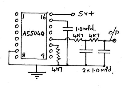
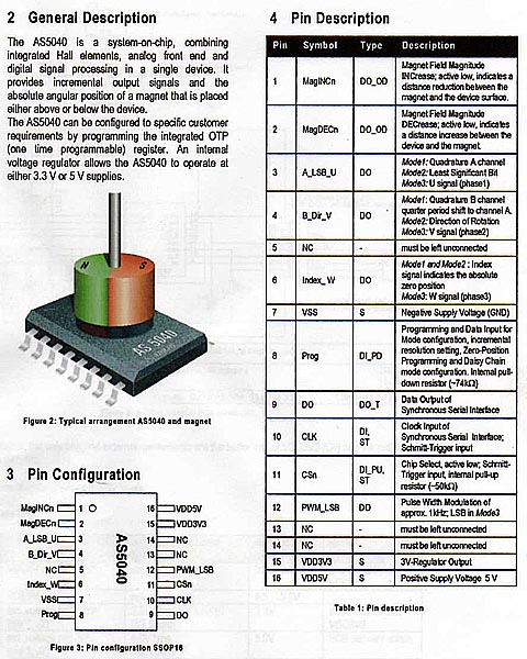
The AS5040 is a system-on-chip, combining integrated hall elements, analog front end and digital signal processing in a single device. It provides incremental output signals and the absolute angular position of a magnet that is placed above or below the device.

This device is manufactured by austriamicrosystems. The full details can be found on their website at :-http://www.austriamicrosystems.com/

The AS5040 can be configured to specific customer requirements by programming the integrated OTP (one time programmable) register. An internal voltage regulator allows operating the AS5040 device at either 3.3 V or 5 V supplies.

The AS5040 chip consists of a ring of hall elements placed at the center of the IC in a circle of 2.2mm diameter. The hall elements pick up the field of a magnet placed above this  hall array. This information is digitized and fed into a digital signal processor which calculates the angle of the magnet with a resolution of 0.35 degrees or 1024 positions per revolution at a sampling rate of 10 kHz.

The digital angle information is available in several formats; as a serial 10 bit data stream, as a pulse-width modulated (PWM) signal or as a quadrature incremental signal.
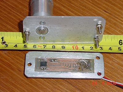
Physical Details

The chip itself is very small, measuring approx. 7.8 mm x 5 mm and has 16 pins and  can be built up to replace the potentiometers in many types of antenna rotators giving a far more accurate and consistent readout than the original setup as there aren't any  mechanical  contacts to wear. The only moving part is a small rare-earth magnet 6 mm in diam. that needs to be attached to a shaft and placed ~ 0.5 -5 mm above the AS5040. I recommend that you purchase the correct magnet for this.

Assembly of a Sender Device for a Beam Indicator (The Electrical side!)

As we are only interested in the analog output the circuit is simple, a regulated +5volts to pin 16, a 4k7 pull down resistor from pin 11  plus a 1.0 mfd buffer capacitor from pin 15  to GND.  Analog output is taken from pin 12 through 2x.4k7 resistors and 2x.1.0mfd caps to avoid loading the output and provide some filtering. Output voltage is 0 volts at 0 degrees up to +5 volts at 360 degrees. I intend using a digital readout setting it up so that 360 deg gives me 360 on the readout.

Now the Mechanical Side (A prototype)

As can be seen from the photo the chip is very small and good soldering skills are required. This board is much larger than required as it was designed for  digital output which John VK5DJ is working on.  The photo shows the bearing machined up with the magnet attached to the 1/4" shaft. You will notice that I made a small aluminium frame for the circuit board to strengthen it. This assembly is mounted on the three screws attached to the face plate and is adjusted for the correct spacing between the IC and the magnet. A smaller circuit board  25 mm square could be made which shouldn't require any frame , and the bearing and shaft from an old pot could be used. The whole assembly would then be no larger than the original pot.