|
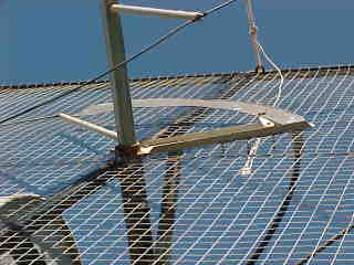
HOME BREWING A HELIX, VK5ZAI STYLE After using a 12 x 12 el. crossed Yagi on 2m. for a year or so for satellite work, mainly AO-13, AO-10, UO-22 and KO-25. I decided to construct a helix to make some comparisons. At this stage I suggest that you read my article on "A Satellite Tracking Antenna" to get an idea on how the antenna is mounted. The elevation pivot is only 3m. above the ground and the booms are end mounted so it is not a major job to swap things around and compare the results. Information was obtained from numerous publications including "The Satellite Experimenter's Handbook", "Satellite Anthology" both ARRL publications, Dr J.D. Kraus's "Antennas" as well as some personal input from a friend the late Vern "Rip" Riportella WA2LQQ. Construction of the helix antenna is mechanically a little more difficult than a Yagi and requires a reflector behind it to function properly. This reflector should be 1 wavelength diameter for best results, although you can get away with 3/4 wavelength. Another disadvantage is that it has to be wound either R.H.C. Polarization or L.H.C. Polarization. Points in favour are it's wide bandwidth, being capable of operating 20-30% above and below its design frequency thus being useful for the weather Sats. etc. It is also very forgiving when it comes to its dimensions when constructing. CONSTRUCTION The design frequency for this antenna is 145 MHz. The main boom is 25 mm. sq. galvanized steel tube with a 1.6 mm. wall thickness, and 5m. long. This is for a 10 turn helix, and allowing approx 400mm. to end mount it in a larger tube attached to the reflector. Each turn has a pitch or spacing of 454 mm. so if you wish to add or subtract turns to suit your own personal requirements just add or subtract 454 mm for each turn, as they are evenly spaced. I used 12mm. fibreglass rod for the insulators cut to a length to give the helix a radius of 325mm. These were spaced 227 mm. apart on opposite sides of the square boom. I first drilled a 9 mm. hole through both sides of the boom 25 mm. from the front end, then every 227 mm. along the boom. Then re-drill every alternate side only, with a 12 mm. drill to take the 12mm. fibreglass rods.
The ends of these rods should be machined or ground down with a shoulder so as to fit into the 9mm. hole on the opposite side of the boom which will stop them going right through. I used a good epoxy glue to hold them in place, however they shouldn't come out once the helix is wound on them. The outer ends of these rods are V notched and a small hole (2-3 mm.) is drilled 12 mm. from the end and parallel to the notch to tie on the helix wire and hold it in place. Note : when gluing these rods into place make sure that the V notch in the end will line up with your helix coil so it fits snugly. This will depend on whether you use LHCP or RHCP. In my case I used RHCP. I used 3mm Diam. (approx) copper wire for the helix, this is not critical, thin tubing could also be used. As the impedance of a helix is in the vicinity of 140 ohms, it requires a matching device to feed into 50 ohm cable. This 1/4 wave matching strip is made from a piece of copper sheet .5 mm. thick (not critical). Scribe an ark 525mm. long on it, with a radius of 325 mm., this is the middle, now scribe 2 more arks to this; one 25mm. larger, and one 25mm smaller. Cut out this strip 50 mm. wide, round one end and drill a hole 25 mm in from this to take the centre pin of an "N" type connector. Cut the corners off the other end of the strip to form a point. When assembled you will solder this to the feed end of the helix allowing 25 mm. overlap for a strong solder joint. The helix can be any number of full turns, with the matching strip making an extra 1/4 turn. Now to make a earthed mounting plate for the "N" type connector, I have chosen to mount this connector on the boom rather than on the reflector. Doing it this way means that the antenna and matching section can be removed as one assembly if required. Get some thick walled tubing (water pipe) that will neatly fit over the boom and cut a off a piece 20 mm. long to form a collar. Drill and tap this collar in two places 120deg. apart so it can be locked onto the boom. Now get another piece of copper (or galv. iron) approx 350 mm. long by 50mm wide and .5 mm thick and braze this to the collar on the opposite side to the locking screws. Drill a hole 325 mm. out from the centre of the of the collar and mount the N type connector, also drill two 6mm. holes approx. 100 mm. from each end of this mounting plate so it can be fastened to the mesh reflector with the aid of a backing plate made of the same material and 2 machine screws, the mesh being sandwiched between the two plates. ASSEMBLY After gluing the support insulators into the boom carefully wind the helix coil, tying it onto the end of the support insulators as you go, start and finish at a support leaving around 25 mm. extra at the feed end to solder on the matching section. Now slip the collar with the bracket and "N" connector attached onto the boom until it is about 50 mm from the first insulator. NOTE: The matching section does not follow the same pitch as the helix coil, this is how it is tuned for the best SWR. In my case the matching strap ended up with only about a 50mm pitch for the 1/4 turn. The threaded end of the connector faces rear-wards and fits through the mesh reflector when fully assembled. Solder the matching section to the end of the helix, butting it right up to the first support then the other end onto the connector. The antenna is now ready to fit into the mounting tube on the reflector assembly. I haven't described this but I would suggest making up a frame of 25 mm. sq. tubing (similar to mine) and covering it with a mesh rather than a solid panel to lower the wind loading. In the centre of this you will have to fit a thick walled tube with 2 lock bolts to take the boom. After fitting the boom to the reflector assembly fasten the plate with connector to the mesh with the aid of the backing plate and machine screws. TUNING THE ANTENNA Leave the collar and lock bolts loose at this stage and connect up your coax and rig set on 145 MHz. with an SWR bridge to the "N" connector. Now slide the boom in and out to obtain the best match. It should be possible to get close to 1:1, on mine the junction of the matching strip and start of the helix was only about 45 mm. from the reflector. When you are happy tighten up all the lock bolts on the collar and boom support and recheck the SWR. and the job's done. PERFORMANCE As I don't have an accurate means of checking antenna gain all I can do is compare it to the12 x 12 el. Yagi that I used to use. Gain wise it is similar however I found that it had less dropouts on AO-13 and AO-10,. At present I am receiving AO-40 TLM at up to 20 over S9. I would be interested in hearing from anyone that builds this antenna or a similar one. I have thought of building a helix for 70 cm. and comparing it with my 21 x 21 el. 70 cm. Yagi. but it all takes time and at present 2.4 GHz is more important to get going. Best 73's de Tony. VK5ZAI. |